
Near-field intra-body Communication
Building a near-field intra-body communication device
Thrilled by the idea mentioned in “When Things start to think” by Neil Gershenfeld i started to build a near-field intra-body communication device to transmit data through a body by capacitive coupling.
Everything written down in this post is based on the original paper by Thomas Guthrie Zimmerman “Personal Area Networks (PAN): Near-Field Intra-Body Communication” – published at the MIT in 1995.
Original paper by Thomas Guthrie Zimmerman: http://www.cba.mit.edu/docs/theses/95.09.zimmerman.pdf
Workshop at etextile-springbreak
Using the body as a communication channel is an interesting approach to send sensor-data from one part of the body to another part of the body – or to another body. This may be very useful for e-textile projects. Especially when it is not possible to use conductive material to transmit data.
The outcome of this project was presented in a workshop at the etextile-springbreak 2018: http://etextilespringbreak.org/
And at the etextile-summercamp 2018: http://etextile-summercamp.org/2018/
The goal of the workshop was to come up with a simple circuit to demonstrate the principle of a capacitively coupled data-channel involving as less parts as possible.
Disclaimer: While the project suggests to carry a transmitter close to the body, the project presented here does not allow this. When the transmitter-circuit is too close to the body the signal gets disturbed and transmission may fail. Shielding the transmitter-circuit may help. An updated version of the circuit may solve this problem.
You can find the presentation here: PAN workshop
Human body – a perfect conductor
- internal resistance (blood, inner organs): ~250 Ohm / meter
- isolated with skin in order of mega- to giga-ohms
- internal impedance can be considered negligible
In general terms a PAN transmitter perturbs the electrical potential of the environment and the receiver detects these perturbations. Another way to state the communication mechanism is to say the transmitter is capacitively coupled to the receiver.
The current return path is provided by the air (dielectric) and earth ground (dielectric and conductor)
Electric Field Diagram
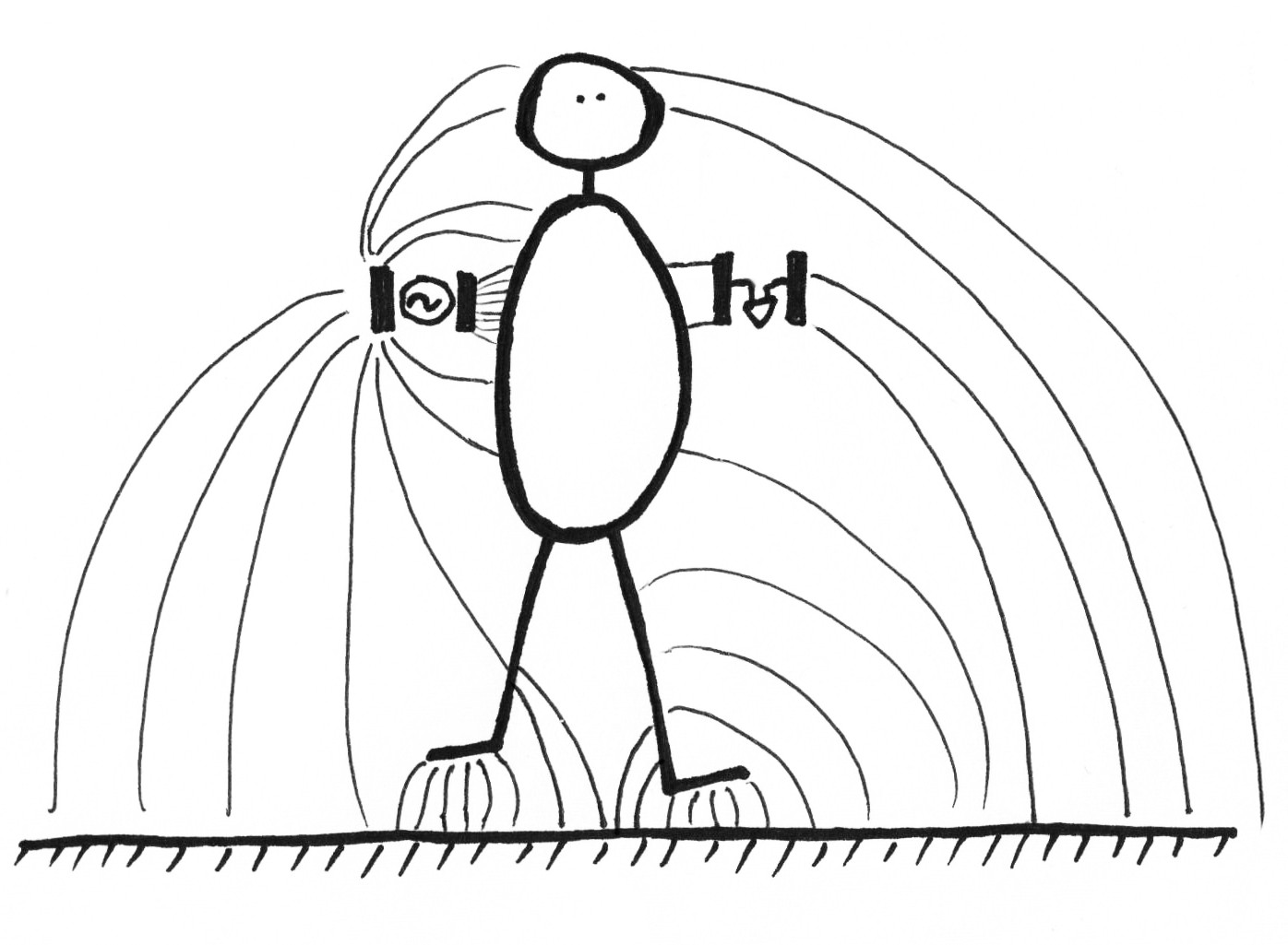
Left side: transmitter
Right side: receiver
PAN Diagram

Transmitter
To transmit data we use On-Off-Keying (OOK) with a carrier wave of ~333kHz which is turned on/off for high/low bits respectively. To perturb the electric potential nicely we drive the electrode with an amplified square-wave using an oscillating circuit. The oscillating circuit consists of a coil and a capacitor in series which is driven with the circuits resonance frequency. To calculate the resonance frequency of the circuit you can use this webpage: http://www.1728.org/resfreq.htm
This generates a higher-voltage sine-wave out of the input low-voltage signal.
Make sure to electrically isolate the electrodes to avoid resistive coupling, we only want to couple capacitively. Dependent on the components used, direct contact to the human skin may draw to too much current from the receiver and break it.
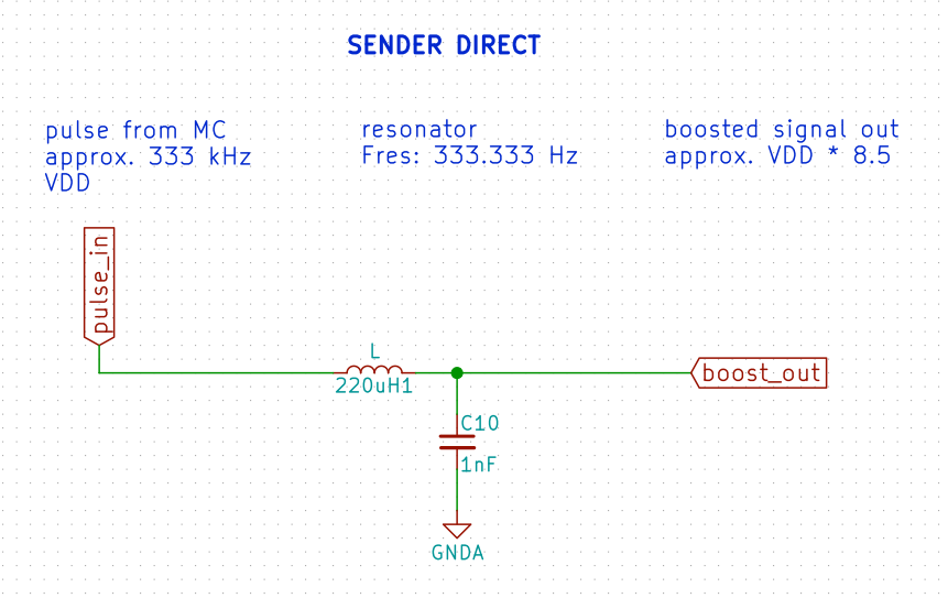
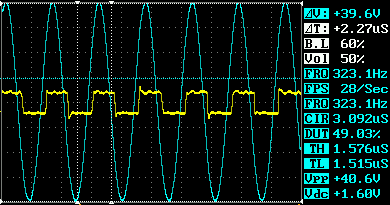
For our purpose we are driving the oscillator directly from a micro-controller pin. The input voltage of ~3.7V from a lipo-battery is amplified to ~35,6 V peak-to-peak:
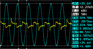
The disturbed square-wave (yellow) is expected, we are only interested in the sine-wave on the output.
For a more detailed information about resonator circuits, please have a look here: http://hyperphysics.phy-astr.gsu.edu/hbase/electric/serres.html
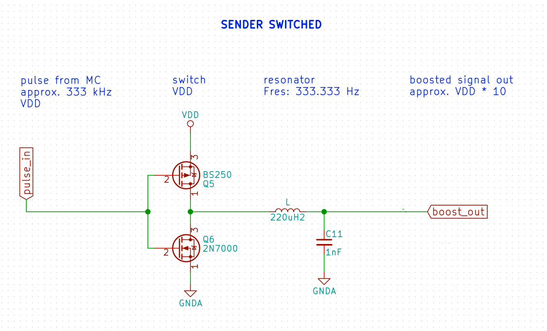
Switched version:
Using a switched version to drive the oscillator circuit shows a cleaner square-wave and gives a bit more amplification (39.5 peak-to-peak):
Switched Driver with higher voltage
If you want to drive the oscillator with higher voltage to get a even higher output voltage you can use a circuit like this:

Be aware of too high voltage which is unsafe to use!
(48V GND-to-peak might be a maximum you want to use on your body)
General Information about oscillator circuits:
Find general information and formulas about oscillator circuits: http://hyperphysics.phy-astr.gsu.edu/hbase/electric/serres.html
Frequency calculator: http://www.1728.org/resfreq.htm
Receiver
The receiver needs to pick-up the signal. For this we need to filter, amplify and clean (threshold) the signal. The circuit is using two envelope followers to smooth out the signal and to avoid breaks in the bits.
Make sure to isolate the electrode to avoid resistive coupling, we only want to couple capacitively.
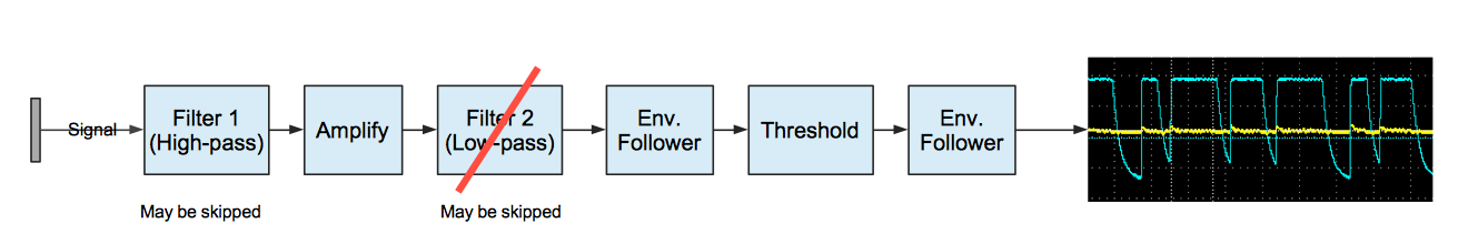
The complete receiver circuit looks like this:
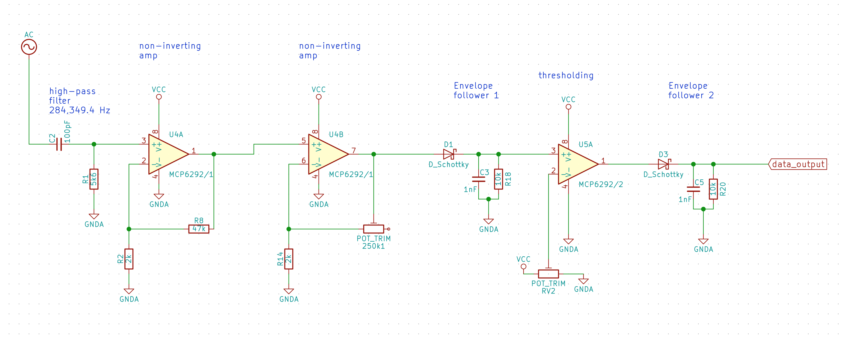
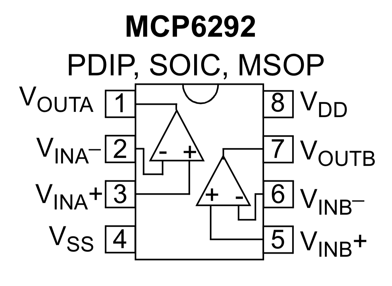
We are using a Rail-to-Rail, Single-supply op-amp: MCP6292
Reading Data from an Arduino (or similar)
Connecting data output to a device directly may change the earth-ground coupling of the circuit and therefore the sensitivity of the receiver.
In order to read data from the receiver we are using an opto-coupler to decouple the grounds:
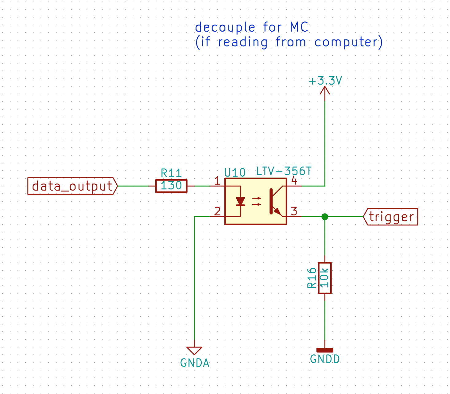
e.g.: reading data-output with an Arduino connected via USB to a computer adds a big capacitive-plate to the circuit. If the computer is connected to earth-ground (connected charger) the circuit directly grounds to earth and therefore changes its behavior (usually it becomes more sensitive)
The opto-coupler may be skipped when reading data-output directly with a micro-controller (e.g. Attiny).
In any way, decoupling the receiver circuit i a good idea.
(take care if you want to measure the circuit itself to use the correct ground)
Encoding Data
Data is encoded using On-Off-Keying (OOK) where a Logic 1 turns the carrier-wave on and a Logic 0 turns the carrier-wave off. For the workshop we are using a period of 200 microseconds for one bit. Using a carrier frequency of 333kHz a logic 1 contains ~66 cycles of the carrier wave, enough time to be sure we got a high-bit. This allows a data-rate of about 5000 bit per seconds. To identify the start of incoming data we send a 8-bit preamble in the form of 10101010. Only when this preamble is detected the decoder accepts bits as data.
We are using a simple serial protocol to transmit the data similar to RS232 with one parity-bit and one stop-bit. (In another version of this project the timings and protocol could be aligned to RS232 to spare the use of a hand-written decoder/encoder.)
Manchester Encoding would be another strategy. This would allow transmitting the data-clock, the receiver would not need to know the exact timing of the data.
Decoding
Decoding strategy is like follows:
The decoder starts with being in preamble-mode. Only if a preamble was detected the decoder accepts data in data-mode.
Whenever the decoder detects a rising-edge on its input-pin a logic 1-bit is detected and pushed into either preamble-data or data. It also starts a timer with a short offset for the next expected bit. When the timer is executed a ~300 micro seconds later we can read the next bit (0 or 1) on the input pin and start another timer with exactly 200 microseconds. If the incoming bit was a 0-bit and the next bit is a 1-bit, the rising-edge will happen before the next timer-interrupt and starting over the procedure. If the next bit would be the same as the last bit, the timer would fire after 200 microseconds to read the next bit.
This strategy avoids timing-shifts, as it re-calibrates the timing every time a high-bit is detected. Slight shifts in timing may happen if the same-bit value is transmitted more often.
This could be fixed by using Manchester encoding.
Please find the kicad-project, code for a attiny-transmitter and an Arduino-recevier here: https://github.com/i-n-g-o/intrabody-PAN
2 Comments
Comments are Disabled
[…] Project: experimenting with near-field intra-plant communcation. http://ingorandolf.info/building-a-near-field-intra-body-communication-device/ […]
[…] the full post here: http://ingorandolf.info/building-a-near-field-intra-body-communication-device/ Kicad-project and code: […]